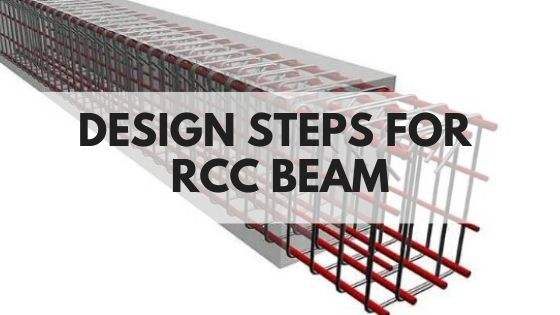
Bar Bending Schedule (BBS) is a document that contains the type, size, bending shape, quantity and the total length of all the reinforcements used in the member.
Thus, Bar scheduling is a way of listing rebars details for each structural member.
It is prepared to estimate the total amount of steel required for that structural member.
The schedule can be prepared by in the following manner
A typical Bar Bending Schedule generally consists of 8 Columns:
1. Bar Number: The bars are categorised as Main Bars, Anchor bar, Crank bars etc, and in a structural member, various types of bars may be used. In the schedule, they are assigned 1,2,3 etc.
2. Bar Mark: Bar mark is assigned to every type of the bars, such as a-a mark for the main bar, b-b mark for Cranked main bar, etc.
The bar mark is transferred from structural detailing drawing to the bar bending schedule.
3. The shape of Bending: This is the most important column in preparation of Bar Bending Schedule, as the total length of that specific bar, used in the structural member, is found out through this column.
Every bar is provided with hooks or bends at the end, in any Structural member. The hooks are provided to satisfy the minimum development length requirement for the component.
The hooks provided, are generally two types—
- Semi circular hook: The shape of this hook is semi-circular type. The length of the semicircular hook taken as the 16 times the diameter of the bar. In case preparation of the bar bending schedule, length of the hook taken as 9d, where Do is the diameter of the bar.
- L-hook: The shape of this hook Is of L shape. The length of the L hook is taken as 8 times the diameter of the bar. In preparation of Bar Bending Schedule, the length of the hook considered as 6d, where d is the diameter of the bar.
Sometimes, bars are cranked in several Structural members, to take up the negative moment, which may develop due to partial fixity. In case Crank bars are provided, the length of the bars required Is more than that of the straight bar. The extra length is taken as the 0.42d, where d is the diameter of the bar(In case of 45° Crank)
4. No of the bar: It contains the total number of similar bars provided in the member. In case of calculation of stirrups or links, the following formulae may be adopted—
Nos. = ( Clear span – effective cover) / (centre to centre distance of the stirrups) + 1.
Note: “1” accounts for the open end Structure.
5. Length of the bar—In here, the length of the bar is determined on the basis of the shape of bending of hooks.
The length of the bars can be found out by following formulae—
- Straight main bars
Clear span = Cover + 2 × 9d (for semicircular hook) or 2 × 6d (for L hook)
- Main bars with a crank on both side—
Clear span = Cover + 2 × 0.42d (2 for crank at both side) + 2×9d or 2×6d
- Stirrups or links—
2 × (Breadth + Depth) + 24d (in case of two-legged stirrups, accounts for extra length)
6. Weight of one bar: It contains the weight of each bar. It can be calculated from the following formulae—
Weight of the bar per metre Length (in kg) = 0.00618 × d^2
where d is the diameter of the bar taken in mm.
7. Total length: It can be calculated by multiplying the number of similar bars, with the length of each bar.
8. Total weight: It can be found out by multiplying the unit Weight of the bar with the total length, obtained earlier.
After preparing the schedule, the total weight of steel required can be found out by summarizing the total weight of each specific types of bars. Total length required can also be found out similarly.
Read More:


